I have an old Fender Sidekick 15 guitar amp, and I wanted to use a TC Electronics G-Major 2 rack mounted effects box with it. But the G-Major 2 requires line level inputs and outputs, and the amp does not have effects loop jacks. I decided to look into modifying the amp so that it would work with the G-Major 2.
The Sidekick 15 is at the low end of the Sidekick series of amps. I found schematics for some of the other amps in the series and found that they had effects loops jacks: pre-amp out, power-amp in. It appeared that a good place to insert the jacks is near the master volume potentiometer.
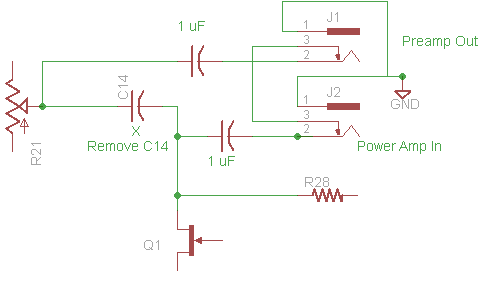
I decided to remove C14, a 1 uF capacitor. I ran a wire from the potentiometer side of the capacitor to the pre-amp output jack and ran a wire from the other C14 lead to the power-amp input jack. The following schematic shows the details:
I used switched jacks. When neither jack has a cable plugged into it, the pre-amp output is connected to the power-amp input and the amp behaves normally. With a cable plugged into either of the jacks, the link between the preamp and the amp is broken. I use the G-Major 2 by connecting the pre-amp output from the amp to the input of the G-Major 2 and connecting the output of the G-Major 2 to the power amp of the guitar amp.
I wanted to protect the guitar amp from DC voltages that might appear on the effects box input or output, so I put a 1 uF capacitor at each jack. The extra capacitors are perhaps unnecessary as effects boxes probably already filter the DC out; however, I wanted to the safe.
When no cables are plugged in, this makes the resulting capacitance that replaces C14 be .5 uF instead of the 1 uF provided by C14. To my ears, there were no noticeable differences between the modified amp and the unmodified amp, but you might want to experiment with the capacitors.
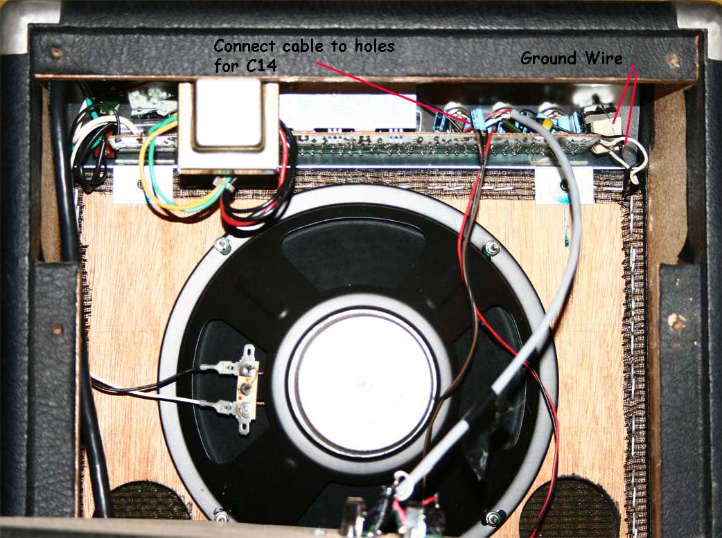
I found it difficult to completely remove the amplifier board to make the modification. I was able to remove the transformer for the power supply and remove the board enough to unsolder C14. I then used shielded cable and soldered one wire to each of the two holes where C14 had been. Finding a place to solder the third wire, ground, was more difficult. I finally soldered this wire to a bare wire near the right side of the PCB (looking from the back).
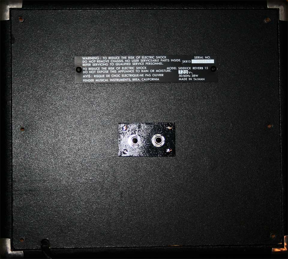
I made a small aluminum plate to hold the two jacks. I drilled two large holes using a brace and bit to allow clearance for the jacks. The back cover is made of particle board and split a bit during drilling; however, the jack plate covers the holes nicely.
This image shows the back of the case with the jacks installed:
This image shows the cable connections to the amplifier PCB:
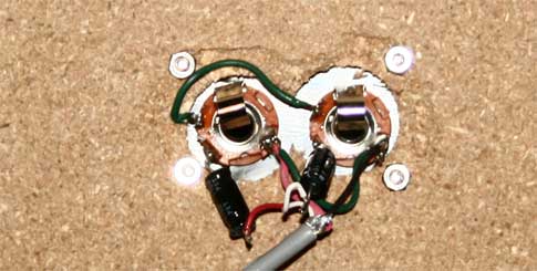
This image shows the connections to the jacks:
Modify your amplifier at your own risk. Unless you have experience with electronics design and repair, you risk damaging your equipment. Because AC line voltage is used in the amplifier, there is a shock risk. I'm not a real engineer and do not warrant the steps outlined here in any way.
I am writing this months after I finished the modification, so some of the information is based on potentially faulty memory.
Feel free to mail questions or comments to me at benjy at tuxcat.com.