I wanted to experiment with a radio-controlled clock using the WWVB time signal. I found a number of pages on the web using the C-Max Time Solutions CMMR-6 receiver module; however, it is difficult to find in small quantities. I found that PV Electronics in the UK sells a similar receiver. There are two models with the difference being the size of the loopstick antenna that comes with the unit:
My wife ordered one of these for me as a gift. Delivery time to the States was very reasonable, and the price is also reasonable. The device functions as advertised.
Due to lack of knowledge, I had some trouble using the receiver. These notes should be useful for first time WWVB clock builders.
| WWVB Modulation | WWVB sends time data in two formats: the legacy pulse width modulation and the newer phase modulation. The SYM-RFT-60 receives the legacy format, so that format will be discussed in this paper. |
| Data Encoding | WWVB transmits data at a rate of 1 bit per second. Transmitter power is reduced by 10 dB at the beginning of each second. Full power is restored in 800 milliseconds to indicate a marker bit, 200 milliseconds to indicate a logic 0, and 500 milliseconds to indicate a logic 1. |
| The SYM-RFT-60 Inverted Output | The logic output from the receiver matches the time of reduced carrier. The output is a logic 1 for 800 milliseconds for a marker bit, a logic 1 for 200 milliseconds for a logic 0, and a logic 1 for 500 milliseconds for a logic 1. |
| Pulse Width | The pulse width times read by an Arduino Mini Pro are typically shorter in duration than the values given above. The microcontroller reading the pulse widths should accept pulse widths that are not exactly what is expected from WWVB. |
| Reception | Reception of the Very Low Frequency (VLF) can be difficult depending on the time of day, the time of year, the location with respect to the WWVB transmitter, and the location of the antenna with respect to house windows. The best time of day for WWVB reception is when the receiver location and the WWVB transmitter are both at night. |
| Alignment LED | The LED on the SYM-RFT-60 indicates
each time a pulse is received from WWVB. If there are no pulses,
try a different time of day and try to position the antenna near
a window facing the WWVB transmitter. As noted above, reception is
best when both the receiver and WWVB are in the night. The broadside
of the antenna should be pointed toward Ft. Collins.
The LED should blink once per second. The duration of the flashes will vary depending on the type of bit. If you see more than one flash per second, the problem is likely caused by a source of interference such as a nearby computer. |
| Data Frame | Each data frame ends with a marker bit, and each data frame starts with a marker bit, so two marker bits in a row mark the beginning of a frame. Marker bits occur every ten seconds as the frame is transmitted. Some bits are unused and are transmitted as a logic zero. Numeric values, such as the day of the year, are encoded in BCD. There are also logic bits for indicating DST, leap years, and leap seconds. |
| Error Detection | There is no error detection code sent with the data, but noise and other reception problems can cause invalid time data to be received. The microcontroller software should confirm that the marker bits occur at the proper place in each data frame and check the BCD values for sane values, e.g., "38" is not a valid hour. Heuristic rules can also be employed in clocks that have already been set such as checking for a WWVB time that is close to the current time. Another technique is to read more than one frame from WWVB and compare the set of frames for consistency. |
| Delay | By the time a full frame has been received, the time specified in the frame is one minute out of date. For example, at 01:22:00 UTC, the marker bit that starts the frame is sent. WWVB then sends the time as 01:22:00. At the end of the frame, the time is 01:22:59. So a clock being set from WWVB should be set to 01:23:00 at the beginning of the next marker bit. |
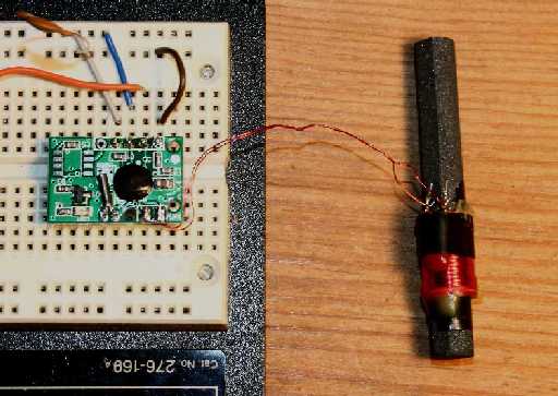
The receiver consists of two parts: a receiver board and a loopstick antenna. Two wires from the antenna must be soldered to the receiver board. Besides the A1 and A2 connection points for the antenna, there are four connections on the receiver board. Vdd is +3 to +5 volts. GND is ground. The PON lead must be grounded to power on the module. The TCON is the serial output from the receiver and can be connected directly to popular microcontrollers such as the Arduino.
I recommend experimenting with the receiver before connecting it to a microcontroller as nearby electronic equipment can interfere with WWVB reception. Connect the receiver to a power source and ground the PON lead and use the on-board LED to monitor device. The LED should blink once per second if the device is receiving WWVB. Some of the pulses will be longer than others as data is encoded using the pulse width.
With a nearby computer, the LED might have a blink rate that is faster than one bit per second. See the "Interference" section for details. If the LED doesn't flash, try a different location or wait until nighttime. A brief touch to the antenna contacts will typically cause an LED flash if the circuit is functional but not receiving a WWVB signal.
The loopstick has maximum gain broadside to the loopstick. Repositioning the antenna can be helpful in improving reception.
My first attempts at using the WWVB receiver involved connecting the receiver to an Arduino Mini Pro that was connected via USB to a computer. Debugging messages were sent over the USB connection. The nearby computer caused the receiver to produce a stream of short pulses in the 10 to 100 millisecond range, completely obscuring the one bit per second data.
Rather than deal with shielding issues, I decided to use the Arduino and a serial LCD display. I was unable to find a suitable shielding method as the Arduino and display interfered with the receiver. I finally used ferrite beads on the longest power and data lines. Although this arrangement seemed to tame the system, further experimentation is needed to determine exactly what complement of ferrite beads are needed or if they were indeed the solution to the interference. Good engineering techniques, such as using the shortest connections possible, might also improve reception.
Here are some others' attempt at shielding:
There are many sources of information about WWVB on the web:
The data frame contains the UTC time and date. It also contains a UT1 correction. (UT1 is the principal form of Universal Time based on astronomical observations and deviates from UTC slightly.) There is also a bit that indicates if the current year is a leap year. Two bits are used to indicate when DST is changing, and there is a leap second bit.
Minutes, hours, the Julian date, and year are encoded in BCD. Unused zero bits are interspersed between the BCD digits. The table below shows the data frame layout. I call the first bit after the start of frame marker bit 0:
| Bit(s) | Usage |
|---|---|
| 0-2 | Tens of minutes bits 40, 20, 10 |
| 3 | Unused = 0 |
| 4-7 | Units minute field 8, 4, 2, 1 |
| 8 | Marker |
| 9-10 | Unused = 0 |
| 11-12 | Tens of hours 20, 10 |
| 13 | Unused = 0 |
| 14-17 | Unit hours 8, 4, 2, 1 |
| 18 | Marker |
| 19-20 | Unused = 0 |
| 21-22 | Hundreds of days 200, 100 |
| 23 | Unused = 0 |
| 24-27 | Tens of days 80, 40, 20, 10 |
| 28 | Marker |
| 29-32 | Unit days 8, 4, 2, 1 |
| 33-34 | Unused = 0 |
| 35-37 | UT1 sign |
| 38 | Marker |
| 39-42 | UT1 correction |
| 43 | Unused = 0 |
| 44-47 | Tens of years 80, 40, 20, 10 |
| 48 | Marker |
| 49-52 | Unit years 8, 4, 2, 1 |
| 53 | Unused = 0 |
| 54-55 | Leap year, leap second |
| 56-57 | DST indicator |
| 58 | Marker - end of frame |
| 59 | Marker - start of frame |
If the leap second bit is set, there will be one extra second at the end of the current month, e.g., 58, 59, 60, 00 instead of 58, 59, 00. See page 29 of WWVB Controlled Clocks: Recommended Practices for Manufacturers and Consumers. (Alternative link) For information on the DST bits, see page 21 of the NIST Guide. When DST is in effect, both bits are set. On the day that DST starts, the first DST bit is set to 1 at 0000 UTC. The second bit changes to 1 24 hours later. The bits change to 0 in the same order starting on the day that DST ends.
Note that by the time a frame has been received, the date and time are one minute in the past. One way to handle this situation is to decode a frame, verify that the format appears correct, add one minute to the time, and set the local clock on the beginning of the marker pulse that starts the next frame.
Many DIY WWVB clocks are built around an Arduino processor. I connected the output of the WWVB receiver to data pin 2 of the Arduino, and attached an interrupt routine to the pin. The interrupt is triggered when the level of the pin changes:
attachInterrupt(0, pulse, CHANGE) ;where "pulse" is the name of the interrupt handler function. In the "pulse" routine, I track the pulse width of WWVB data by saving the time in milliseconds at the start of a pulse and computing the pulse width at the end of the pulse:
void pulse() {
  int sig = digitalRead(wwvbPin) ;

  // If we've going high after a low, this starts a pulse.  Get the time.

  if(sig == HIGH && pulseStart == 0) {
    pulseStart = millis() ;
    return ;
  }

  // If we see a high but haven't seen a low, just ignore the transition.

  if(sig == HIGH) {
    return ;
  }

  // If we haven't seen a start of pulse and have a low, just ignore.

  if(pulseStart == 0) {
    return ;
  }

  // We got a pulse.  Compute the duration.

  pulseEnd = millis() ;
  pulseWidth = pulseEnd - pulseStart ;
  pulseStart = 0 ;

  // This interrupt routine continues building a data frame and setting
  // the clock.
The pulse duration can be tested to see if the data bit is a marker
bit, a logic 0, or a logic 1.
Because this is an interrupt routine, some care must be taken with regard to the length of the routine and the operations that are performed. In my clock, the interrupt routine uses an FSM to look for the marker bits and fill in a data frame. When the frame is complete, it updates a clock object. Functions that require interrupt processing, such as updating the date and time on an LCD display, are initiated from the main program.
I build a clock based on these notes. See Benjy's Accurate Clock for details.
Mail questions or comments to me at benjy at tuxcat.com.