Benjy's Nixie Clock
 |
 |
|
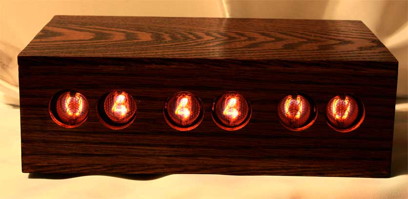
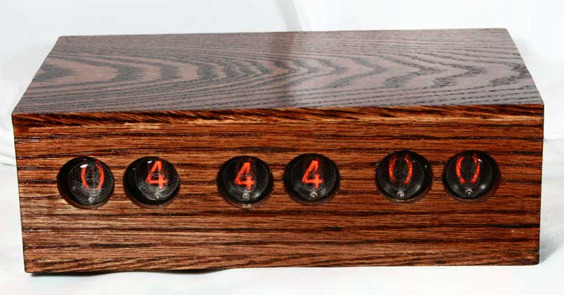
Benjy's Nixie Clock is complete. The final effort was
building a case for the clock: The Nixie Clock Box Project. After
putting off the project for a few years, I finally decided to build a box
out of oak.
Thanks to the following for suggestions and encouragement during the Nixie Clock Box Project: Sue Ellen Cline, Gene Bard, Mike Barts, and Scotty Bolling. Click images for a larger view. November 9, 2009 | |
 |
 |
|
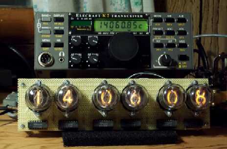
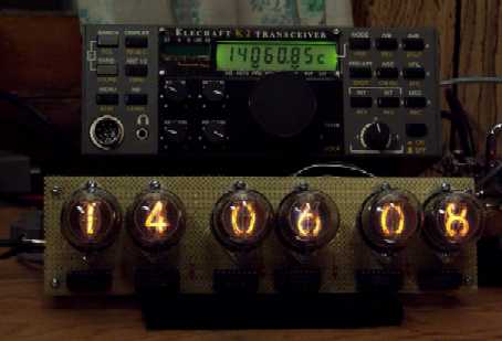
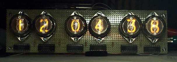
These pictures show the nixie tube clock in "K2" mode, which displays the
operating frequency of the Elecraft
K2 transceiver. When the clock is powered on in K2 mode, it sends an
"AI1;" command to the K2, which causes the transceiver to report its
frequency immediately and then report frequency changes. The clock
parses "IF" responses from the K2 with an FSM and displays the frequency.
Click the images for a larger view. June 6, 2006 | |
 |
| The clock now has a set mode. When the set switch is activated,
the seconds value is
set to zero, and two potentiometers are used to set the hours and minutes
values. To set the hours value, the hours pot is turned until its position
is analogous to the value displayed on the hours display. Once there is
a match, the displayed hours value tracks the position of the pot, and
the hours can be set. The minutes pot works in a similar fashion.
I find I can set my nixie clock must easier and faster than all the
other digital clocks I have.
August 14, 2005
It works! The clock keeps time. To set it, turn off the clock, then wait until noon or midnight and turn it on. I still need to complete a better method to set the clock, make a copy of the 12V to 170V DC-to-DC converter onto the board, and build a case. I also want to build a serial interface so the clock can be used to display the operating frequency of my Elecraft K2 transceiver. March 15, 2005 |
Clock History
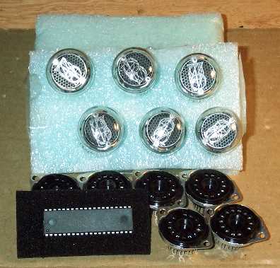 |
It needs a little work!September 2002 |
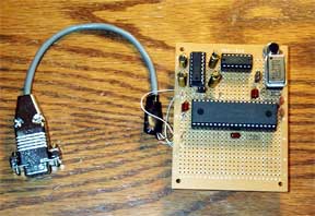 |
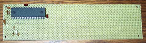
This is my MC68HC908GP32 programmer/proto board.The HC908 will form the heart of my nixie clock.April 2003 |
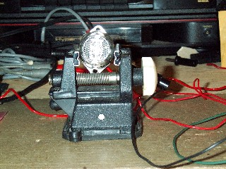 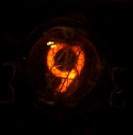 |
Tube checkoutI checked out one of the tubes using a half-wave power supply. November 2003 |
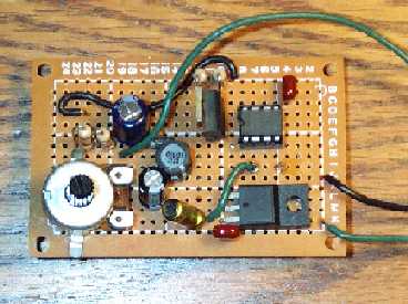 |
DC-DC Converter
|
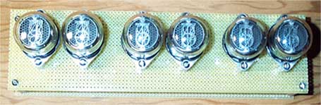 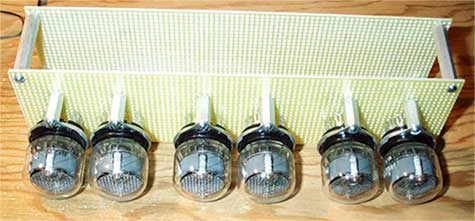 |
Main BoardsThe top board contains the nixie tubes and will hold the six driver chips. The bottom board will hold the microprocessor. September 2004 |
 |
Keeping TimeThe heart of the clock is the HC908. I've written a program to configure the timebase to operate at 4 Hz. The timebase interrupt routine counts ticks, and the main program outputs seconds, minutes, and hours on the processor's I/O lines. Still to come is the code that will allow the time to be set. Potentiometers will be used to allow the user to set hours and minutes.
November 2004 |